
Protocol Simulator Board 1 for Decoder Testing
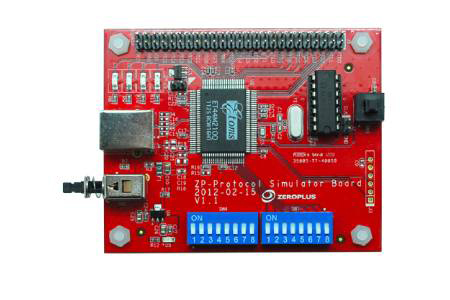
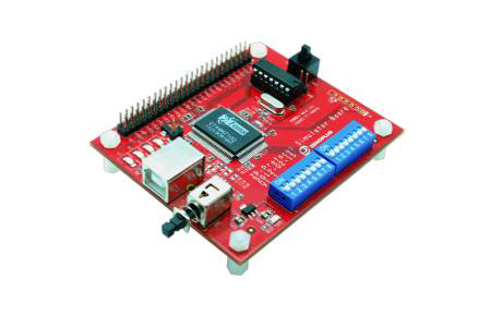
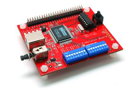
Protocol Simulator Board 1, a demo board for LAP-C Pro: outputs CMD, CLK and DATA bus signals so decoder settings can be checked against known traffic.
Signal Simulation & Demo Boards 1
FM00000192
The Protocol Simulator Board 1 is a versatile bus signal generation tool designed for engineering development and debugging. It simulates a wide array of standard communication protocols (including I2C, SPI, UART, and CAN), enabling users to verify logic analyzer decoding, trigger settings, and system timing without the need for a live Device Under Test (DUT).
Universal Bus Signal Simulator with 100+ Protocol Support
The Protocol Simulator Board 1 is an essential instrument for embedded system development and protocol validation. Supporting 46 bus protocols with ongoing updates, this device excels at simulating high-quality bus signal outputs (including CMD, CLK, and DATA). Designed for seamless integration with Zeroplus Logic Analyzers, it allows for immediate signal decoding and analysis. For instance, when simulating an I2C signal, the board generates complete packet formats—such as Start, Address, R/W, Data, A-ACK/D-ACK, and Stop—streamlining the verification of complex communication protocols.
Features
- Extensive Protocol Support: Simulates 46 protocols, including I2C, SPI, UART, CAN 2.0B, and USB 1.1, with a growing library.
- Accurate Packet Output: Mimics real-world bus behavior by outputting complete packets with start/stop conditions, data bits, and ACK/NACK.
- Instant Decoding Validation: Optimized for use with logic analyzers to quickly verify protocol decoder software and trigger configurations.
- Hardware Control: Integrated DIP switches allow for rapid switching between different communication standards.
- Compact Form Factor: The small footprint (7 x 9.7 cm) ensures easy integration into any test bench environment.
Key Specifications
- Protocol Support: 46 types (including I2C, SPI, UART, CAN, 1-Wire, HDQ, PS/2, I2S, etc.)
- Signal Output: CMD, CLK, DATA bus signals
- Operating Modes: Supports Single Run and Continuous transmission modes
- Status Indicator: D1 signal activity LED
Applications
- Protocol Validation: Verifies the accuracy of protocol analyzer decoding software.
- R&D Debugging: Simulates peripheral signals during early-stage development to accelerate firmware coding.
- Educational Training: Provides standard communication waveforms for teaching electronic engineering and embedded systems.
- Production Testing: Acts as a reference signal source to test the receiving capabilities of production line equipment.
Specifications
| Item | Protocol Simulator Board 1 |
| Bandwidth | - |
| Real-time Sample Rate | - |
| Voltage Range | - |
| Trigger Source | - |
| Trigger Mode | - |
| Auto Measurements | - |
| Interface | - |
| Power Source | Bus-powered via Logic Analyzer (No external power required) |
| Dimensions | 70 x 97 x 25 mm |
| Weight | - |
| Supported Protocols | 1-WIRE, 3-WIRE, 7-SEGMENT LED, AC97, ARITHMETICAL LOGIC, CCIR656, DIGITAL LOGIC, DMX512, DSA Interface, FlexRay2.1A, HDQ, IRDA, I2C, I2S, JK FLIP-FLOP, JTAG2.0, LCD12864, LPC-SERIRQ, LCD1602, LIN 2.1, Low Pin Count, MCU-51 DECODE, ModBus, MANCHESTER, MICROWIRE, MII, MILLER, NEC PD6122, PCM, PECI, PM BUS1.1, PSB Interface, PS/2, SLE4442, SM BUS2.0, ST7669, ST BUS, SD2.0/SDIO, S/PDIF, SPI, SSI Interface, UART (RS-232C/422/485), UP COUNTER, USB1.1, CAN 2.0B , DIGRF |
- Video
 Download
Popular Products

Testing Decoder Settings Before the Target Is Ready
Protocol Simulator Board 1 is a demo board for LAP-C Pro models. It outputs bus signals on CMD, CLK and DATA for the analyzer to decode, so decoder settings can be checked against known traffic without building a test setup. Its protocol list includes I2C, SPI, UART, CAN 2.0B and MII, and Zeroplus states that nearly 100 buses are supported across the simulator boards.
Board 1 covers common embedded and automotive buses. For storage and USB protocols, Protocol Simulator Board 2 covers USB 2.0, eMMC, SD 3.0, Quad SPI and SWD. Both boards measure 7 x 9.7 x 2.5 cm, so the choice comes down to which protocol list matches the decoders your project or course uses, and whether your analyzer supports each of those decoders.