
JK Flip-Flop Analysis: Verify Edge-Triggered Logic
JK flip-flop analysis with Zeroplus logic analyzers: view J, K, clock, preset, clear and Q outputs to verify state changes on the clock edge.

JK FLIP-FLOP Protocol Analysis for Circuit
The Introduction of Protocol Analyzer J-K FLIP-FLOP Application
The JK FLIP-FLOP is mainly applied in the control of the digital signal. It changes the connection mode of Flip-Flops, The JK FLIP-FLOPcan be divided into T-Type Flip-Flop and D-Type Flip-Flop.
With Zeroplus logic analyzers and the JK FLIP-FLOP analysis module, engineers can observe flip-flop input and output states more efficiently, verify edge-triggered logic behavior, and support digital circuit design and debugging.
The Introduction of Protocol Analyzer J-K FLIP-FLOP Analysis Function
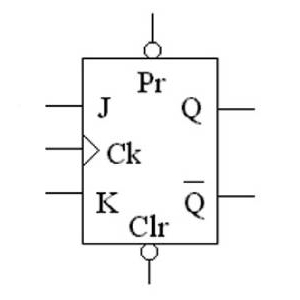
The output of JK FLIP-FLOP starts the state conversion when the changing edge appears on the CP. The other JK FLIP-FLOP starts judging according to the Edge Trigger. It is different from the normal Flip-Flops that the conversion of the state. It doesn’t rely on the values of J and K after the changing edge appears, but it is relative to the values of J and K before the changing edge appears. Engineers needn't do the manual decoding with waveforms when they start developing or debugging checkout by using the Protocol Analyzer JK FLIP-FLOP Analysis Module of Zeroplus Logic Analyzer. According to the Protocol Analyzer Analysis function of Zeroplus Logic Analyzer, the package of the protocol analyzer can be displayed with the cob mode. It makes engineers know the package data of signals at the first time, thereby it can save much time and improve the working efficiency.
- BUS Line: J、J' K、K' CLR PR CP Q、Q'
- Frequency: User Define
- Voltage: User Define
- Area of Project Application: JK FLIP-FLOP Electric circuit Decoding
- Gallery
-
-
 BUS Line: J、J' K、K' CLR PR CP Q、Q', Frequency: User Define, Voltage: User Define
-
- Download
-

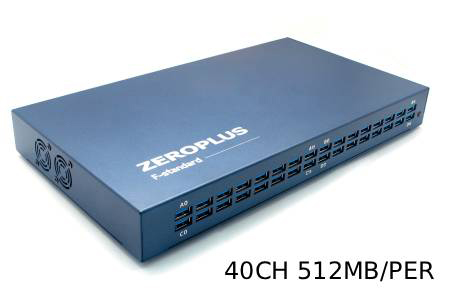
40 Channels High Speed Logic Analyzer
LAP-F140512M | FM00006147
The 40-channel High-Speed Logic Analyzer: Engineered for synchronized multi-bus measurement...
Details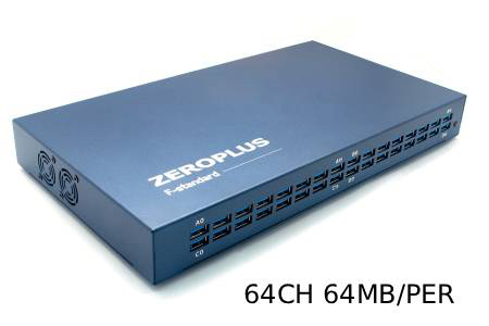
64-Channel Synchronous Logic Analyzer
LAP-F164064 | FM00002619
Harnessing a 64-channel synchronous monitoring core, this system supports internal timing sampling...
Details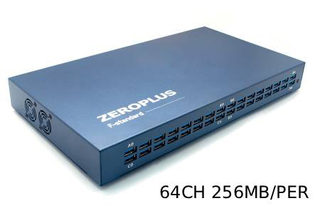
64-Channel Advanced Logic Analyzer
LAP-F164256M | FM00006156
The 64-Channel Advanced Logic Analyzer stands as a perfectly balanced model, integrating 64-channel...
Details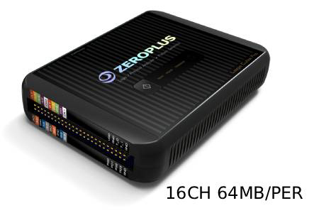
16-Channel Entry-Level High-Performance Logic Analyzer
LAP-C Pro 16064M | FM00007890
The 16-Channel High-Performance Logic Analyzer is ideal for digital development tasks requiring...
Details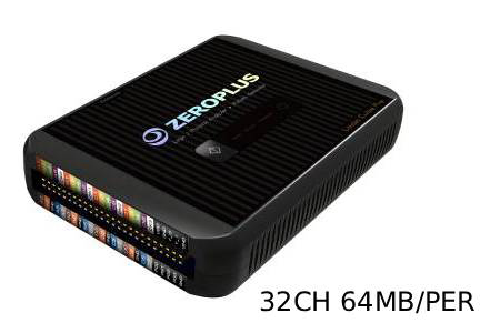
32-Channel High-Performance Logic Analyzer
LAP-C Pro 32064M | FM00007893
The 32-Channel High-Performance Logic Analyzer is ideal for digital system verification tasks...
Details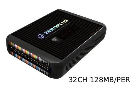
32-Channel Advanced High-Performance Logic Analyzer
LAP-C Pro 32128M | FM00007896
The 32-Channel Advanced High-Performance Logic Analyzer is ideal for development and verification...
Details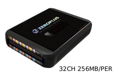
32-Channel Flagship High-Performance Logic Analyzer
LAP-C Pro 32256M | FM00007899
The 32-Channel Flagship High-Performance Logic Analyzer is ideal for advanced development environments...
Details
16-Channel Standard Logic Analyzer
LAP-C 16064 | FM00000118
The 16-channel standard logic analyzer is ideal for daily debugging needs such as microcontroller...
Details
16-Channel Enhanced Logic Analyzer
LAP-C 16128 | FM00000116
The 16-channel enhanced logic analyzer is designed for embedded development, digital debugging,...
Details
ProCision System Stability Analyzer
FM00011874
The ProCision is a high-density system stability analyzer engineered to replace limited 4-channel...
Details Download
Popular Products
Verifying Edge-Triggered Flip-Flop Logic
A JK flip-flop changes state on the clock (CP) edge according to the J and K values present just before that edge, so a fault can only be confirmed when all inputs and outputs are captured on the same time base. The analysis uses J, J', K, K', CLR, PR, CP, Q and Q', with frequency and voltage set in the decoder configuration options.
The decoded states are displayed as packets for circuit testing, so engineers and students do not have to read each edge by hand. For analyzer selection, note that one flip-flop already uses nine signals; a 16-channel model covers a single stage, while circuits with several stages captured together need a larger channel configuration.