
Modbus Protocol Analysis for PLC Communication
Modbus protocol analysis with Zeroplus logic analyzers: decode ASCII and RTU frames with header, address, function, data and LRC/CRC fields.

ModBus Protocol Analysis for Industrial Control
ModBus can simplify communicating transmission among PLC. Compared to RS-232、RS-485, its efficiency is much higher. It is widely applied in power controlling systems, elevators, big printer platforms, etc that are equipped with PLC. With Zeroplus logic analyzers and Modbus analysis capability, engineers can capture ASCII and RTU packets, decode commands, and verify LRC/CRC16 more efficiently for PLC communication debugging, industrial equipment integration, and field control system validation.
Function Introduction
ModBus has two types of serial communication modes, they are ASCII mode and RTU mode, the two types of modes have synchronous transmitting speed rates and different checking means. The length of each package is 10 bits under ASCII mode, and it includes following parts:
● Start Bit (1bit): Its content is fixed as"0" Data Bit (7bits): It consists of 0 ~ 127, transmitting direction is (LSB to MSB) Synchronous Check: It checks whether data is correct, if start Synchronous Check, its length is 1 bit, if not, then the bit does not exist.
● Stop Bit: its content is fixed as "1", if start Synchronous Check, its length is 1 bit, if not, then the length of Stop Bit is two bits.
User can easily analyze Header / Adder / Function / Data / LRC / CRLF in signals by using the functions of Zeroplus LAP, and it is more efficient for user to change signal state into picture state by using functions of special bus Each package contain 8 bits field and 1 bit code in RTU mode, contents of code is as following:
● Start Bit (1bit): Its content is fixed as"0" Data Bit (8bits): It consists of 0 ~ 255, transmitting direction is (LSB to MSB) Synchronous Check: It checks whether data is correct, if start Synchronous Check, its length is 1 bit, if not, then the bit does not exist.
● Stop Bit: its content is fixed as "1", if start Synchronous Check, its length is 1 bit, if not, then the length of Stop Bit is two bits. RTU mode provides the function of CRC16 data verification; it enables the special bus function of Zeroplus LAP to easily display CRC16 and verify contents of documents very quickly.
- Bus Line: ModBus
- Frequency: 19.2KHz
- Area of Project Application: Electronic Control System
- Gallery
-
-
 Bus Line: ModBus, Frequency: 19.2KHz
-
- Download
-

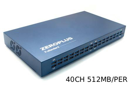
40 Channels High Speed Logic Analyzer
LAP-F140512M | FM00006147
The 40-channel High-Speed Logic Analyzer: Engineered for synchronized multi-bus measurement...
Details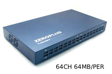
64-Channel Synchronous Logic Analyzer
LAP-F164064 | FM00002619
Harnessing a 64-channel synchronous monitoring core, this system supports internal timing sampling...
Details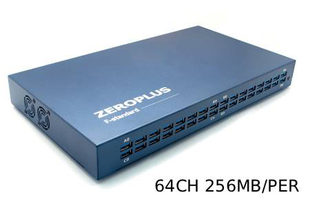
64-Channel Advanced Logic Analyzer
LAP-F164256M | FM00006156
The 64-Channel Advanced Logic Analyzer stands as a perfectly balanced model, integrating 64-channel...
Details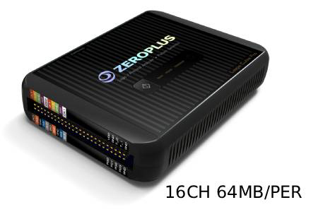
16-Channel Entry-Level High-Performance Logic Analyzer
LAP-C Pro 16064M | FM00007890
The 16-Channel High-Performance Logic Analyzer is ideal for digital development tasks requiring...
Details
32-Channel High-Performance Logic Analyzer
LAP-C Pro 32064M | FM00007893
The 32-Channel High-Performance Logic Analyzer is ideal for digital system verification tasks...
Details
32-Channel Advanced High-Performance Logic Analyzer
LAP-C Pro 32128M | FM00007896
The 32-Channel Advanced High-Performance Logic Analyzer is ideal for development and verification...
Details
32-Channel Flagship High-Performance Logic Analyzer
LAP-C Pro 32256M | FM00007899
The 32-Channel Flagship High-Performance Logic Analyzer is ideal for advanced development environments...
Details
16-Channel Standard Logic Analyzer
LAP-C 16064 | FM00000118
The 16-channel standard logic analyzer is ideal for daily debugging needs such as microcontroller...
Details
16-Channel Enhanced Logic Analyzer
LAP-C 16128 | FM00000116
The 16-channel enhanced logic analyzer is designed for embedded development, digital debugging,...
Details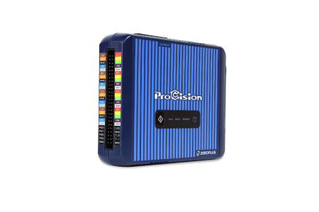
ProCision System Stability Analyzer
FM00011874
The ProCision is a high-density system stability analyzer engineered to replace limited 4-channel...
Details Download
Popular Products
Decoding Modbus ASCII and RTU Frames
Modbus links PLCs and field devices in industrial control systems over serial lines in two modes: ASCII, which sends readable characters checked with LRC, and RTU, which sends binary data checked with CRC16. A wrong function code or a failed check is hard to spot when characters must be converted by hand.
With ASCII or RTU selected in the decoder configuration options, the Zeroplus Modbus decoder displays header, address, function, data, LRC and CRLF fields, so faults are visible during system testing. Modbus serial rates are modest, so selection depends on the mode and baud rate in your installation and on how many field signals must be captured alongside the bus.