
Pattern Generator for LAP-C Pro: I2C, SPI, UART and CAN
Pattern generator on LAP-C Pro analyzers: sends I2C, SPI, UART, CAN and GPIO patterns through 4 channels, defined by importing an Excel file.
Digital Pattern Generators
NX00000163
The Digital Pattern Generator (DPG) is a high-performance signal generation module integrated within logic analyzers. It empowers engineers to simulate various standard or custom digital communication protocols (such as UART, I2C, and SPI) by actively sourcing controlled signals to verify the logic responses of a Device Under Test (DUT). It serves as an essential virtual host tool for hardware debugging and system integration testing.
Professional Active Hardware Verification & Protocol Simulation
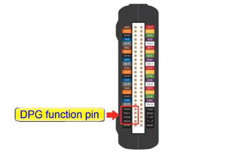
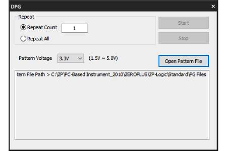
The DPG (Digital Pattern Generator) elevates logic analyzers from passive data acquisition to active hardware verification. Users can define custom waveforms, serial baud rates, and designated output pins (PG0, PG1, etc.) through an intuitive software interface or Excel file imports. By simulating precise digital commands sent to the target circuit before a functional host is available, DPG works in tandem with real-time protocol decoding to quickly validate how a system responds to specific signal sequences, significantly maximizing R&D efficiency.
Features
- Versatile Protocol Simulation: Supports simulation of widely used digital protocols including UART, I2C, and SPI.
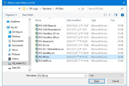
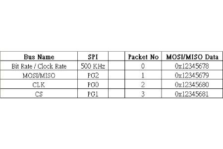
- Flexible Data Import: Facilitates the definition of complex data packets and signal timings via Excel file imports.
- Precise Parameter Control: Allows customization of baud rates, output channels, and signal logic levels.
- Simultaneous Active / Passive Verification: Enables concurrent DPG signal sourcing and logic analyzer acquisition for end-to-end loopback testing.
- Real-time Packet Monitoring: Works with the Packet List view to instantly verify consistency between transmitted and received data.
Key Specifications
- Output Channels: Dedicated PG output pins (model dependent, e.g., PG0, PG1).
- Transmission Rate: Adjustable digital frequencies (e.g., 400 kHz and above).
- Data Formats: Supports Hex, Binary, or customized packet content.
- Compatibility: Seamlessly integrated with professional logic analyzer software suites.
Applications
- Hardware Prototyping: Testing peripheral circuit responses before the master MCU firmware is fully developed.
- Error Injection Testing: Simulating abnormal or boundary condition signals to test system stability and fault tolerance.
- Automated Production Line Testing: Sourcing fixed signal sequences as a baseline for automated Pass / Fail diagnostics.
Specifications
| Item | Digital Pattern Generators |
| Channels | Base on Logic Analyzer |
| Bandwidth Support | - |
| Input Impedance | - |
| Input DC voltage (Max.) | - |
| Input signal level | - |
| Bus Voltage | - |
| Capacitance | - |
| Interface | Logic Analyzer within Software |
| Power Source | - |
| Target Device | - |
| Function | Signal Simulation & Protocol Injection |
| Connection | - |
| Contents | - |
- Video
 Download
Popular Products
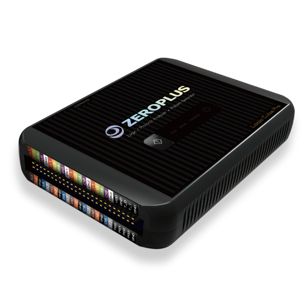
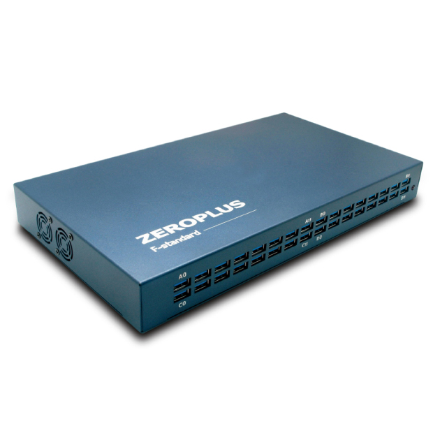

Driving Test Patterns Into a Device
The pattern generator turns the analyzer into a signal source. On LAP-C Pro models it generates digital signals through 4 channels for I2C, SPI, UART and CAN, as well as GPIO, so a peripheral or device under test can be exercised before its controller firmware is finished. Pattern configuration is defined by importing the provided Excel file, so test sequences can be prepared as files.
The pattern generator is listed on the LAP-C Pro 32256M, so confirm whether the LAP-C Pro model you use or plan to order includes it. For a stand-alone adapter that simulates an I2C or SPI master or slave from a PC, compare the I2C-SPI Control Center.